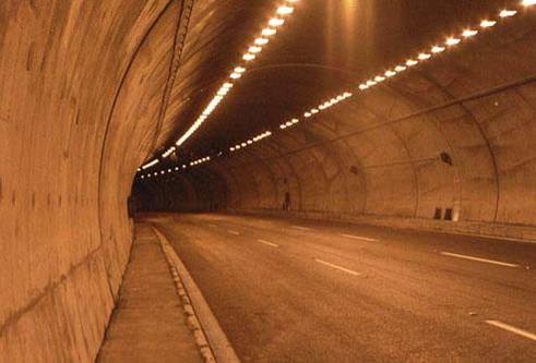
The panels; for the power distribution, emergency power distribution, UPS power distribution and power factor corrections were manufactured and tested in our factory. All the system was build to be controlled by PLC centrally located in Bahçe and also from local controls in the Substations buildings. Each tunnel was equipped with two numbers of 1600 kVA transformers Substations located at each end of the tunnels.
The longest tunnel P3 was equipped with 1 kV axial fans 632 kVA, 1022 kVA and two 381 kVA situated in the middle portion.
LENGHTS OF TUNNELS
P2 AYRAN TUNNEL
South Carriage Way 559 m North Carriage Way 597 m
P3 KIZLAÇ TUNNEL
South Carriage Way 2860 m North Carriage Way 2804 m
P4 ASLANLI TUNNEL
South Carriage Way 1241 m North Carriage Way 1214 m
POWER DISTRIBUTION
In the substations 36/0.4 kV transformers were utilized for feeding the power and illumination.
In P3 Tunnel transformers for the three substations in the tunnel niches were 36/1 kV. 1 kV was transformed in to 0,4 kV in the niches.
In case of power failure each substation had emergency generators. In case of total failure a back up UPS fed illumination to carry on the traffic through the tunnels.
Emergency Generators Feed :
UPS system Emergency ventilation Tunnel illumination as required for emergency operations Substation requirements
UPS system feeds :
Control systems Data acquisition Emergency building lighting
OPERATION PRINCIPALS
All the control were done according to following priorities.
1st PRIORITY Local hand control at Substation buildings 2ndPRIORITY Operation panel in case of emergency. 3rdPRIORITY Substation control center 4thPRIORITY Operation from BAHÇE control center located at 5 km to P2 tunnel. 5thPRIORITY Local automatic controls.
Local manual controls can override all other controls.
On all related panels indication of which location is controlling the system is shown by signal lamps.
TUNNEL ILLUMINATION WAS DEVIDED INTO FOUR SECTIONS.
Illumination of Portal Area
Entrance Illumination
Interior Lighting
Illumination in case of two way traffic in each tube
TUNNEL VENTILATION
All tunnels were ventilated by jet fans operating through the control signals send by CO detectors, dust particular detectors, air circulation direction and velocity detectors.
Ventilation control can be done in three different ways;
Automatic
Manual control
Emergency (Fire) operation.
Jet Fans utilized were:
P2 TUNNEL
South Carriage Way 13 No’s North Carriage Way 12 No’s
P3 TUNNEL
South Carriage Way 78 No’s North Carriage Way 46 No’s
P4 TUNNEL
South Carriage Way 23 No’s North Carriage Way 33 No’s
In P3 KIZLAÇ TUNNEL, in addition to the jet fans, 1 kV axial fans are installed in the middle portion.
The capacity of these fans were 2 pieces 381 kVA, one 632 kVA and one 1022 kVA.
We are proud to design, coordinate and manufacture the elements of such a complete project to Turkish Highway Department.

